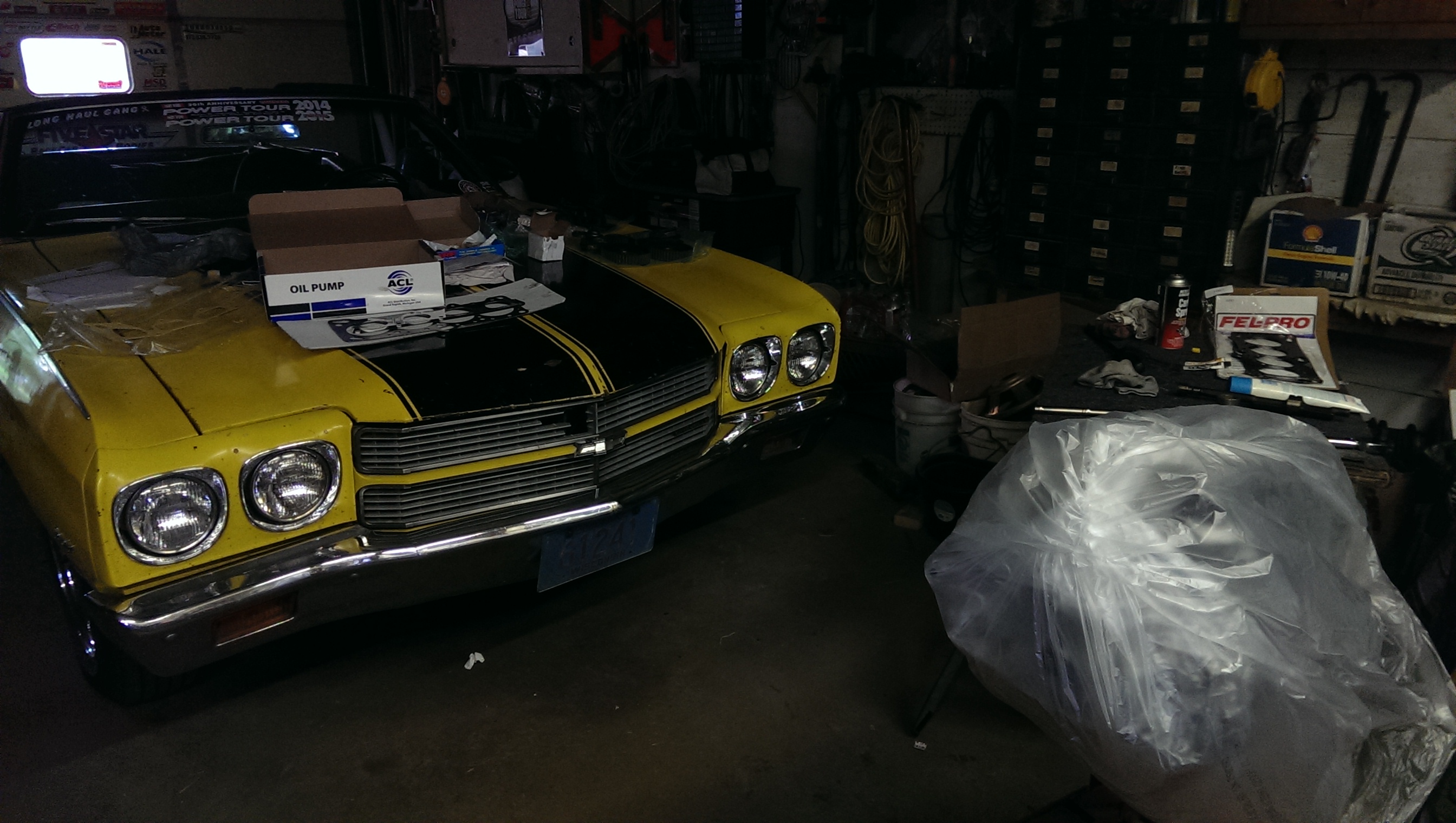
I was supposed to pick up a 1995 Eagle Talon TSi AWD yesterday for a 2002 TSi project (yes, it’s exactly what you think) but was informed that the car had sold as I was hooking up a car trailer. Oh well, Craigslist is a first come first serve deal, and I wasn’t first. Without that to look forward to I decided I might as well work on the DSM I have now. I asked my dad if he was free to help out and give pointers and then headed to the garage to get everything ready. I’ve been slowly amassing the parts I’ll need to make my engine whole again, so I gathered what I had and got ready to find out what I forgot.


The first thing we wanted to do was get the engine on a stand so it would be easier to work with, luckily we were able to find the same bolts we used last year when we stripped the engine. We also set up a small table to hold tools and parts that were needed for whatever bits we were currently working on. My dad has built engines before, but he’s more acquainted with the small block Chevy side of things. The basics are more or less the same though and having his pointers and knowledge is a boon. He knew what tools we’d need and the shop manual knew what procedure we should follow for making sure the crankshaft bearing went in the right way. So we got the crankshaft out and inspected it to make sure there were no scratches on any of the lobes. Weavers had polished it, but it’s always best to double check.


Getting the bearings in is the easy part, you lay them in and push them into place. You do want to take the time to clean everything up first, the smallest bits of dirt or metal can still wreak havoc throughout your engine. My engine had been sitting for nearly a year at this point and rust had taken hold on some of the surfaces the bearings sit on. Armed with some sand paper and carb cleaner, I cleaned up any surfaces that we needed to work with. There wasn’t much to sand here, so I basically cleaned everything and we got to it.


Once we had the bearings in, we used assembly lube in place of engine oil. Assembly lube stays in place and won’t drip away like an oil will, but it also won’t harm the engine when you get the thing running. Generally, any surface that will experience friction needs a good helping of this and it’s also good in case you leave it sit for a bit. We torqued our brand new oem main bolts to the correct spec of 47-51ft/lbs and made sure we could still rotate the crank freely.


Next, we took all the bolts out on the front most cradle and cleaned up the camshaft lobe that the bearing rides on. We have to make sure that when the cradle is torqued in place that there is enough clearance for the crankshaft bearings to get lubrication while spinning, but not so much that there may be play. It’s a delicate balance, down to hundredths of an inch. In this particular instance, the main bearing clearance has to be in the range of .0008-.0020 to be considered healthy for the engine. To take this measurement, we use Plastigauge.
Plastigauge is fairly ingenious, it’s just a long piece of wax that you chop a small piece off of. This piece gets laid on the surface you are measuring, in our case the crankshaft lobe. Then you place the cradle back on and torque it back to spec. Unbolt it again, and then measure how much the wax squished out. Pretty freaking neat!
After you get the measurement, you sand the cradle valley where the bearing sits or the cradle legs to adjust for too tight and too loose respectively. Mine were all to loose. This means a lot of sanding, torquing, unbolting, sanding again, repeat until the bearing clearance is within spec. You can see in the third picture that the Plastigauge has spread further, meaning we had tightened our bearing clearance.


Once we had all four of the bearings in spec, we gave up for the day. We’d already been working on the engine for about 5 hours at that point, and we were not looking forward to doing rod bearing and the sanding that cam along with that. We did, however, take the time to put in assemble the rear main seal and housing because why not. I also stuffed some rags in the cylinders and sanded the block surface a little to remove the little bit of rust that had started.

I awoke the next morning with the hope of getting further on the engine. I ordered the last major part I needed with the money I had set aside for that 1995 Talon, and then headed to the garage for some more learning. Remember sanding? Yep, that’s what I started with. The connecting rods had also developed a bit of rust from sitting, so I hit them with 1000 grit sand paper and cleaned up with carb cleaner. Once I had cleaned the surfaces, I set about replacing the rod bolts. The stock ones will hold the power levels that I’m looking to reach, but it’s one of those “might as well since it’s already apart” sort of things. A set of ARP rod bolts are cheap insurance, there are a lot of parts that I paid just a little more for in the hopes that I won’t have anything to worry about for many miles once this is all back together. The old bolts had to be hammered out, and the new bolts lined up correctly and then carefully hammered back in place.


Not only had the connecting rods rusted a little, but there seemed to be a bit of crud in the piston skirts. Carb cleaner and a bit of air took care of that, and we made sure to re-lubricate piston wrist pins with some heavy motor oil and work them around a little. With that taken care of, it was once again time to focus on bearings. Rod bearings need a clearance in the range of 0.0008-.0020 in the 4G63T engine (the 6 bolts engines anyway).


To check this we first have to install the bearings in the connecting rods and caps, and then get the pistons in the cylinder. Lots and lots of assembly lube is used here, and you also need to gap and align the piston rings. Weavers had me send them the pistons and rings to them while they were going over the engine. They checked the gaps of the piston rings (insert one in the cylinder and measure the gap in the open end of the ring, this is repeated in the top, bottom, and middle of the cylinder in case there is any taper) and installed them for us. All we had to do was align the top two ring gaps (the compression rings) 180 degrees offset from each other. Then we had to get the bottom two rings (oil control rings) set 180 degrees apart from each other, as well as 90 degrees offset from the compression rings. Now, all of these have to be 45 degrees offset from the wrist pin as well, easy right?
Once you get those set, grab a piston ring compressor to squeeze them closed enough that the piston will slide into cylinder with some hammer handle tapping.


One very important thing to remember is to have a cover for the rod bolts while you’re installing the pistons, you really do not want to scratch or gouge the crankshaft lobes with the bolt thread. We used some heater hose that happened to fit over the bolts, problem solved! After guiding the connecting rod into place, we started installing the end caps and checking clearance for the rod bearings. We got very lucky here, and all the bearings were in clearance and didn’t need any adjusting. No sanding? Fine with me.


So we installed pistons 2 & 3 as well and checked those. All within spec, whoop!


With those finished I got my shiny new front case out and started figuring out how to install the balance shaft delete kit that is very popular with DSM builds. Basically, there are two shafts of metal that run from a belt and are used to counter balance engine movement so as to smooth the engine out a bit. The problem is, these are dead weight and the belt lies under the timing belt. When the balance shaft belt decides to go it usually take the timing belt with it. In an interference engine such as this, that means you now have pistons and valves fighting to occupy the same space. That doesn’t work well. So most people that build a 4G63T engine eliminate that possibility.
To do so, you have to replace a few bearings and block of some oil ports that won’t be used anymore. I purchased a kit on EBay (not sketchy at all right?) and studies up on the procedure on VFAQ so I had an idea of what to do.
Step the first, is to plug the giant whole in the front case that one of the balance shafts used to occupy. A freeze plug and some JB Weld insurance did the trick. Next up, you need to install a stubby shaft in place of the other balance shaft, this time run directly from the oil pump. I’ve also been told that when running a stubby shaft you want to use straight cut oil gears as found in the very early engines. Most others come with helical cut gears, as my new front case did. Luckily, my old front case had a pump with straight cut gears, so I took them out and cleaned them. Using a bit of Loctite, I fastened the stubby shaft to the smaller gear where the balance shaft used to be. When reinstalling the gears in the pump, there are dots on either gear to make sure you align them correctly.


I also needed to grab the plug that goes on the other side of the small oil gear. I’m not sure why my new front case didn’t come with one, but I was able to re-purpose my old one after a good cleaning.


With that, the front case was ready to go on.


But first! The other half of the balance shaft delete, which is to remove two bearings from the block and replace them with bearings that have no oil port. If we don’t do this, we’re going to lose a lot of oil pressure, and that’s no good for an engine. In the first picture here you can see the bearing on the right side that we’ll need to remove. The bearing on the left is also there but is hidden deeper in the block. The second picture shows where we just knocked a bearing out, as well as another bearing further in that does not have an oil port, and therefore can stay in. The last picture shows the other side of the block where we have the second bearing we need to knock out and replace.


We used a socket that was just slightly smaller than the bearings to knock them out, you want to be careful not to damage the block or leave any metal shavings in the engine. Once we had the old bearings out, and that second one is particularly fun to fish out, we used the same socket to insert the new oil-port-less bearing. For the bearing that was on the outside of the block, we actually use a freeze plug to completely block that off as we don’t want oil to pass through the space a traditional bearing would leave open.


Make sure you clean up any metal shavings you can find!
By now it was nearly supper time and we were ready to get some grub. I spent a little more time cleaning up the front case bolts, installing the front case (sort of, lots of figuring out which bolt goes where), and then wrapping everything up. I did find out that I needed a pilot bearing and a 5mm allen style socket (my set only goes down to 6mm of course) to get the head put on so I’ll have to grab some more parts this week. Hopefully the next update will see most of the accessories back on, guess we’ll find out. See you next time!


Cars, Computers, & Random Thoughts